Week 14 - Finalize everything...

Friday, 9 November 2012


Finally, I'm already done in week 14..
Presentation in front of assessor done..
But I don't have the opportunity to demo
in front of my supervisor.. =(

A few days before presentation,
I'm quite busy on the design of PCB board
of Arduino.

Below are some pictures during preparing the
PCB Arduino.. :)

1st step :
Design the Arduino circuit in pcb layout
by using Diptrace.
PCB layout of Arduino circuit
2nd step:
Ironing the board by layered it
with a small fabric.
Ironing
3rd step:
Etching by using the Acid liquid.


4th step:
Drilling.
After the drill, the connection is checked 
to make sure when placing the components,
there are connected.

Finally.. the circuit is looks like this.
Arduino circuit done in pcb board
Done on all the steps, troubleshooting need to be do.
This is to make sure the voltage is enough supplied to
the components. At first some of not connection.. by 
place the jumper to the specific connection. Problem 
is solved. 

Next, proceed on the casing.. 
The final look is like in the picture 
below : 
Remote Patient Monitoring System
Poster
Regarding on the pulse oximeter coding..
Sadly to say here, I'm not finding the right 
coding. I had a limited of time, I'm just make
my own program, which I make a condition 
of SpO2, in NORMAL or ABNORMAL.
The result as shown below:

The result is obtained
Transmission of the data and displayed in serial monitor

Overall, it might be not so perfect
because the SpO2 I'm not success 
in obtained the coding.
I'm still grateful to Allah by giving me
the strength and confident to settle all this.
14 weeks struggling  in this final project is 
really worth until success during the 
presentation day.. :)
Thank you to Sir Zul, En.Azmi, Nik.
Not forget to my beloved parents that 
keep on pray for me.. :) 
Friends, thanx a lot.. ;)


Week 13 - APC220 Radio Communication Module

Thursday, 1 November 2012

As salam..

Week 13 already..
Now, I will focus on the
APC220 Radio Communication Module.

What is APC220 ?

The APC220 radio module provides a simple and
economic solution to wireless data communications.
The employment of an embedded high speed
microprocessor and high performance IC creates a
transparent UART/TTL interface and eliminates any
need for packetizing (form data into packets)
and data encoding.

Features

  • Transmit distance up to 1000m @ 9600bps 
  • 256 bytes data buffer
  • High sensitivity (-112dbbm @ 9600 bps)
  • GFSK modulation
  • UART/TTL interface
  • Size: 37x17x6.5mm
I had done by used this module to my 
project. Here are the results:

Heart Rate is displayed in LCD by connecting with the APC220

The measurement heart rate is displayed in serial monitor
Both of the pictures, show the measurement of
heart rate. The data is running at the same time.
How the laptop can received the data is through 
the APC220 that is plugged at the laptop like 
show in the picture below: 

APC220 plugged in to laptop

I'm also tried this transmission of data by the 
distance 1000m. It's successful... :)

Week 12 - Wifi shield is getting problem !

Friday, 26 October 2012

As salam..

Last two days, I had went to Shah Alam,
regarding on the problem of wifi shield.
The problem is like in this video :


I went back to Shah Alam to see Nik and
En.Azmi regarding on this problem.
What I found in solving this matter is :


Clicked the Terminal, for the Local echo and Local
line editting, clicked at the "Force on". Before this
it sets at "Auto". That is the reason why the problem
is happened that show in the video.

Then, you clicked open, it will be ready to type the
AT command.
Before that, we find out the IP address, gateway
and subnet. Below are some of pictures that show
the AT command. Which some of is ERROR,
and finally solved by searching in internet the right
command.

IP address is success
AT command of "AT+WAUTO.." is success

AT command of "AT + NAUTO.. " is success

Below is the AT command by looking on the 
tutorial of Putty I had :

AT command of Putty configuration


By looking on the pictures that had taken
and with the AT command, can see the different.
Some of AT commands are ERROR when type
in the Putty. So, the pictures taken are the right 
command. 
All that, by referring on this link 

When all the AT command is successful.
The wifi also success acted as a server.
But, other problem is come. 
It's not connected to the Arduino.
When looking on the post last week,
at the end, supposedly, the data that type 
in Putty, will be linked to the Arduino, 
but at this time, there is no connecting..
Error is found. We had tried to change the 
arduino uno, but still not connected. Searching in 
internet, if it has any solutions, but still no highlight
to solve the problem.

Finally, En.Azmi and Nik suggested, what if 
change to used a APC220 Radio Communication 
Module.The module is seems like a Xbee. 
Which a complete module with transmitter in receiver.
Here is the picture of 
APC220 Radio Communication Module.
APC220 Radio Communication Module
Since just leave 2 weeks for the presentation,
This module also relate with transmit data to 
the laptop which can view directly by a clinician.
So I've decided to buy this APC220.


Week 12 - Done on setting up the wifi shield !

Tuesday, 23 October 2012

As salam..

Regarding on the post last week, I had decided went
to Shah Alam to meet En.Azmi regarding on the
problem of wifi shield V2.2. I met En.Azmi and Nik,
one of person that had experienced in Arduino.

Nik helped me to set up the wifi.
At first, it still give no result.
I'm worried it might be hardware problem as
what Sir Zul said.
Nik keep tried. Alhamdulillah..
the wifi shield V2.2 is gave a response.
That means the wifi is well-functioned.

The way he sets up, he used a Putty configuration.
Which Putty also the software that functioned
same like WizSmartScript. The software is looks
like as shown below :

First step :
1)   Set the Putty Configuration with serial line
      which is the COM port and also the speed
      as a baud that fixed in 115200.

2)   Clicked "Open".
       It will show as below:


By display this, you can send AT commands to Wifi
module through your serial terminal according the
command. As you see [OK] that display in the Putty,
it's a response from the wifi. When the response is
received, means the wifi is in a good condition.

At the same time, I had be informed by Nik,
before I send the AT commands, I should find
out the IP address, gateway and also the subnet
of the wireless router.

To find it, clicked "Start", type "run" and
type cmd, and OK.
It will display the IP address, gateway and
the subnet.

When in AT commands, the end number
of IP address should change with the other
number. Like an example, IP address for
the wireless router: 192.168.10.101,
so, it need to change to 192.168.10.105
The number can be change with any
numbers.
The reason you change this IP address is
to make this wifi shield as a server.

When it is done, you put the IP address
and port in Putty configuration like below :

The port is 4000 is fixed.
As Nik mentioned, this is common port
in networking line. The, clicked OPEN.
It will display like below :

You can see the configuration is already
display the IP address that we set in AT command.
So means the wifi is already acted as a server. Then,
by opening the serial monitor, it will display
"Connect..."
when the "Welcome to dfrobot" is typed in putty,
the serial monitor will receive the "Welcome to dfrobot".

So, means the wifi is successful.
All this really helpful for me to proceed my part
by follow the instruction as Nik already mentioned
to me.
Thank you to Nik and also En.Azmi. :)

Week 11 - Wifi Shield is arrived !

Thursday, 18 October 2012

As salam...

Post for the week 11..
Wifi Shield V2.2 is already arrived.

All the documentations that related with this wifi
are printed out.
The software of WizSmartScript is downloaded.
The wifi is ready to setting up.

The WizSmartScript Software
1st step:
I need to set the COM port, that is 11 and the baud
of 115200. Then clicked the "Start Script".
The result should be display as below by referring in the
set up document.

When the setting up is success will proceed on the
tutorial. The tutorial is also by using the WizSmartScript:


1)  Checked the COM port depends on your
    Arduino com port and also the baud must be 115200.
2)  Clicked "Wizard".

It will show this:

But for my part, it is not displayed as above.
Mine is appeared as shown in this video :


I've met Sir Zul regarding on this problem.
He also tried  by doing the same steps as I had done..
The result still error and when find the wizfi, still state
ERROR.
He said it might be the hardware problem.
Basically, this wifi need a wireless router.
But when to find the wifi module there is no
related with wifi router, it is related with
COM port Arduino only.

Sir Zul suggested, to call the person that I bought
this wifi. Informed them the problems.
Unfortunately, the person in charge is the seller not
a technician. So for me to communicate with the
techinician must be through an email. For sure,
it's complicated for me if not face to face.

Other solution, Sir Zul had a contact person with En.Azmi.
The person who are in experienced in Arduino.
The coincidence En.Azmi also sell this wifi shield V2.2
DF Robot. When Sir Zul informed him the status of
wifi and he gave a good response through the phone call.
I've decided to see him on the spot at Shah Alam.
I wish the wifi is going well. :)

Week 11 - SpO2 coding.....

Monday, 15 October 2012

As salam..

This week already week 11..
Sensor done !
Coding for heart rate done !
Wifi on the way....
Coding for pulse oximeter still on research...

Especially on the Arduino coding..
Actually already in month, I'm still in searching this
pulse oximeter program..
I had search in YouTube about the pulse oximeter
project. Mostly the result is displayed in waveform..
The coding mostly not share with public..
and some of are not for pulse oximeter..
but for heart rate..

I had asked my seniors that had an experienced in this
pulse oximeter. One of that I asked.. I'm explore the
coding. The coding that used is JAL program and the
measurement of pulse oximeter in this program
is same with the heart rate. So the reading for heart rate
and pulse oximeter are same.
For sure the reading of pulse oximeter is wrong here.
We know the normal reading for pulse oximeter is about
98-100.
I'm also doing my research in library which looking
on the final year report. One of is related with pulse oximeter
and that one the only used Arduino program.
The other used a PIC program but when I'm looking on
the program, it shows measurement on heart rate.

Generally, calculation SpO2 in theory is

Oxygen Saturation =  C(HbO2)/ (C(Hb) + C(HbO2) x 100%

C (Hb) = Concentration of deoxygenated hemoglobin
C (HbO2) = Concentration of oxygenated hemoglobin

The comprehension about the pulse oximeter is like below:


When the finger is placed between the light source and the light
detector, the light will pass through the finger to reach the 
detector. Part of the light will be absorbed by the finger and
the part not absorbed reaches the light detector.

The amount of light is absorbed by the finger depends on
many physical properties and these properties are used by the
pulse oximeter to calculate the oxygen saturation.

The amount of light absorbed depends on the following:

1)   Concentration of the light absorbing substance.
2)   Length of the light path in the absorbing substance
3)   Oxyhemoglobin and deoxyhemoglobin absorbs
      red and infrared light differently.

The different of absorbent of the red and infrared light
will give the different wavelength. Which the Oxy Hb is
absorbs more infrared light than red light.
For the Deoxy Hb is absorbs more red light than infrared
light. By this it can be related with the calculation in theory.
The problem here is to get in coding is a big problem
for me. Whatever it is I should find it !

Week 10 - Pulse Sensor is arrive ! :)

Friday, 12 October 2012

As salam..

Alhamdulillah..after a few weeks, the Pulse Sensor
that I had order for the last few weeks is arrived.
I received the new upgrade of Pulse Sensor.
This one is the Pulse Sensor Amped.
The different with the previous one, this new sensor
produced a nice waveform where can see the PQRST
waveform.

It's really excite me to try this one..
Before I try, as mentioned in the previous post,
I have to prepare the sensor by doing the right
technique.

Done on that, I'm trying the sensor by uploaded the
Arduino programme and the Processing.
Below is the result :


The next video is show when the sensor is out
from the fingertip:


From the videos, it proved that sensor is more 
better than old one. I mean the graph is better 
compare with the last sensor. 
Conclusion for the sensor is settle.
Just leave for pulse oximeter coding.
I need to proceed my research on the 
suitable coding.  


Week 9 - Plethysmograph.. turn to Pulse Sensor

Saturday, 6 October 2012

Hello..

Regarding on the Plethysmograph circuit, my supervisor
had asked me just used a pulse sensor.
Since, I'm actually already don't have any idea to solve
the matter of the circuit, I've thinking to buy the pulse
sensor. During semester break I had make an order the
new Pulse Sensor from the U.S. For sure it takes 2 weeks
for me to receive that.

For the old Pulse Sensor I had show to my supervisor on
the problem of the sensor. What he found is the back of my
pulse sensor not glue. It supposedly glue by using hot glue.
That is the reason my sensor just function for a couple of
time. What happen if not glue the back of the sensor, it
might a short circuit.

Here is the technique to prepare the pulse sensor and I
should apply it when the new one is arrive.. :)

First step:
A thin film of vinyl to seal the sensor side
The pulse sensor is an exposed circuit board, and if
touch the solder points, it could short the board or
introduce unwanted signal noise. The vinyl sticker
offers very good protection for the underlying circuit,
and rate it 'water resistant' that means:
It can stand to get splashed on.

Second step:
The hot glue is put at the back sensor
While the glue is still very hot, press the Pulse Sensor
glue-side-down onto the sticky side of a piece of tape.

After the hot glue is cooled
Once the hot glue has cooled, the tape will peel off
very easily. Check and make sure that there are not
exposed electrical connections. 
Next, trimming the extra glue at the side sensor.
This is final look of the sensor after glue
Then stick the velcro dot at the back of glue sensor 
and make a finger strap with velcro tape. Both of this 
things are included in the packet of Pulse Sensor.
The Pulse Sensor is make as the finger strap
The Pulse Sensor is ready to use.. :)


Week 9 - Research on the Internet Enabled Microcontroller

Tuesday, 2 October 2012

As salam..

Regarding on the post last week..
Since the plethysmograph still in the same result.
I had met my supervisor, Sir Zul and informed him
the problem that I faced. 
He suggested for me to buy the exactly type 
of sensor that shown in the schematic circuit.
There are SFH 487 for IR and 
SFH 309 FR for photodetector. Currently I'm
already had the SFH 487. Just need to make an 
order for SFH 309 FR. For me to wait the delivery 
might takes few days.

I'm proceed to find out the "Remote System" part in
my project, whether by applied the internet or wireless.
Refer on my proposal for the last FYP Semester 1,
I had found the ioBridge IO-204 was quite 
compatible to act as a remote. This IO-204 is applied
by connecting to a Local Area Networking (LAN) using 
10/100/1000 Base-T-Ethernet and then establishes and 
encrypted connections to ioBridge web server.

But unfortunately, this module not sold in Malaysia.
Even, I buy this module at the out of country, if any 
problems come it might difficult for me to be refer of.
Then, this module also used the internet cable, and 
the price is quite high because plus with the shipping.
Other thing, I'm thinking when the time I want to 
present my project, where can I plug in the internet cable.
From the few matters, I have to decide to find other 
module that might be solve the matters and most important 
is compatible with my "Remote System". 

So, I've found a few modules that related with Arduino
and mostly I found is better to be used 
a wireless application. The Arduino also has the 
Wifi Shield Arduino but in Malaysia still not listed in 
market. 

Then I found DF Robot. Mostly the module from 
DF Robot is related with Arduino.
So, by doing the survey with comparing the price
and the features. I've decided 
to choose Wifi Shield V2.2 for Arduino. 
Below are some pictures of modules that I found:

Wifi Shield Arduino (prefer to use this)
WiFi Shield V2.1 For Arduino (802.11 b/g/n)
Wifi Shield V2.2 (final choose)

The reason I'm chosen this Wifi Shield V2.2:
(a)   This product is listed in Malaysia market.
(b)   Easy for me to refer if has any problem with this module.
(c)   It's related with Arduino
(d)   This provide the documentation how to set up and the tutorial.

I'm already make an order and waiting for the delivery.

Week 8 - Testing Plethysmograph circuit

Saturday, 29 September 2012

As salam..

This post is continued from the previous post.
The research on the Plethysmograph is helped
for me to test the circuit that shown in the schematic
below:
pulse plethysmograph circuit
Pulse Plethysmograph Amplifier Circuit


Sensor
The sensor consists of a light source and photodetector.
Whereby the light is shone through the tissues and 
variation in blood volume alters the amount of light falling 
on the detector. The light source and detector can be 
mounted side by side to look at changes in reflected light 
or on either side of a finger or earlobe to detect changed 
in transmitted light. The infrared filter of the phototransistor 
reduces interference from fluorescent lights, which have a 
large AC component in their output.

Amplifier
The amplifier uses an LM358 dual op-amp to provide two 
identical broadly-tuned band pass stages with gains of 100.
The circuit runs from a single 6V battery and the output 
zero is offset by about 1V by referring everything to an 
internal common line at a voltage set by a pair of 
forward-biased silicon diodes. This is convenient for 
interfaces with a 0-5V input.

Components are not critical but the two 2.2uF capacitors 
must be able to stand some reverse bias so they should be 
non-polarized. To get the expected result, the potentiometer 
is adjusted, so that the output is about 2V peak. The trace 
should look like this:
calculating heart rate experiment results
Heart rate trace

calculating heart rate results
Pulse Plethysmograph results during deep breathing
Actually this experiment's result is achieved by using the 
PicoLog software. From this software the expectation 
waveform will display clearly as required. 

So, I'm just trying the circuit by using the oscilloscope 
in lab. The sensor I changed to LDR and Red LED.
The result I obtained is shown as the pictures below:

When the sensor not touched
When the sensor is touched
The first waveform is produced is quite same with
the expected result just had the noise.
The problem I had is, when I'm connected to 
ground, the waveform is not displayed at above.
It was displayed like too much of noise and 
no pattern of waveform can be seen. When I'm 
not connected the ground the result is displayed 
at above.

The potentiometer I'm already adjusted but the 
waveform is still not give any pattern if I'm 
connected to the ground. If I'm disconnected the 
ground the waveform is displayed. 

The sensor I'm already change to the 
IR transmitter and receiver. But the result still the 
same.
The circuit was constructed

Week 7 - Research on the Plethysmograph

Friday, 14 September 2012

As salam..

As the previous post, I'm still on the research the
circuit. For this week, I'm proceed to do a research
for the next circuit that might be suitable for the
measurement of heart rate and pulse oximeter.

I'm also asked the senior that had an experienced
in a project of pulse oximeter and heart rate. Mostly 
few senior that I met, told me that they are used 
plethysmograph. That was my first time heard that kind
of name. ISo that, I'm doing my research on that 
plethymograph circuit. What I found is :

Plethysmograph is an instrument for measuring changes in
volume within an organ or whole body (usually resulting 
in the amount of blood or air it contains). 
A photoplethysmograph (PPG) is a plethysmograph that 
uses optical techniques. A pulse oximeter measures oxygen 
saturation level (SpO2) and is also a PPG.

It can measure the change in the volume of arterial blood
with each pulse beat. This change in blood volume can be 
detected in peripheral part of the body such as the fingertip
or ear lobe using a technique called photoplethysmography.
The pulse oximeter that detects the signal is called a 
plethysmograph (or 'Pleth' for short).

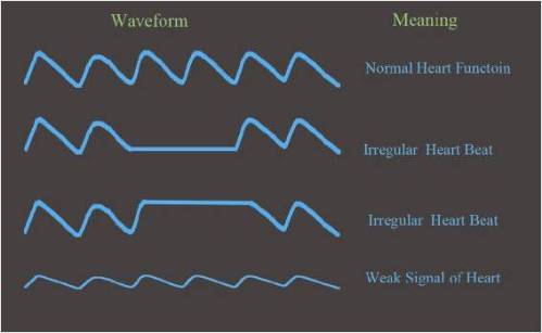
The blood flow is normally shown as a waveform using a 
graph. It can provide useful information regarding the heart 
condition. Below is the different waveform with the status 
of heart beat.


Heart Rhythm
Pleth is useful to detect irregular heart rhythm. The regular
beating or contraction of the heart moves the blood throughout
the body. The heart beating pattern is clearly displayed by 
watching the pleth waveform. This is important to observe the 
pleth waveform because from that the doctor can know 
the condition of the patient's heart.

Signal Strength
Weak signal is indicated by the amplitude of the waveform. 
If the signal is too low, it would affect the accuracy and 
functioning of the pulse oximeter. If your oximeter is not 
giving the correct result, check if the signal strength is too 
low.

There are several causes for the weak signal:
  • Low blood perfusion
  • Dirty sensor or LED lights
  • Improper positioning of the oximeter
All the info I found is help to understand what is actually 
Plethysmograph.. Next post will be about the circuit of
plethysmograph.

(Week5 - Week 6) Research on circuit

Friday, 7 September 2012

As salam..

Since Week4 is the Eid holiday..
I'm continued my research and testing the circuit in
Week5 and Week 6.. :)

As the previous post I had mentioned that my pulse
sensor is already failed in functioning.
This post will focus on the a few circuits that I had
done that is compatible to measure the heart rate
and pulse oximeter. So, I had make some research
about some circuits. Below is the first circuit that I
had tried that used Arduino programme.

Schematic circuit of Pulsometer

The Op-amp that used in this circuit is LM324.
IR led and LDR are used in this circuit.

LM324 is a 14 pin IC consisting of four independent 
operational amplifier (op-amps) compensated in a 
single package. Op-amps are high gain electronic 
voltage amplifier with differential input and a single-ended 
output. The output voltage is many times higher than the 
voltage difference between input terminals of an op-amp.

Theses op-amps are operated by a single power supply 
LM324 and need for a dual supply is eliminated. They 
can be used as amplifiers, comparators, oscillators, 
rectifiers etc. The conventional op-amp applications can 
be more easily implemented with LM324. Here are the
LM324 pin diagram and description. 

LM324
Pin diagram
Pin description

Below is the video that shows successful of the circuit.


As shown, there is working prototype that graphs pulses 
on computer that based on data from serial port. Work 
is going on signal processing to output pulse data, not only 
digital pulsations.

The goal is to build a separate digital/analog sensor for
arduino with possibility  to log data for future reference.

Below is the video of the result that I obtained from 
the schematic circuit that shown in early of this post.


As you can see the graph not stable like the one that
success. When I touched the LDR sensor, it gave the
shape of waveform. When I am not touched it, it became
a flat graph. I had tried to adjust the variable resistor,
but the result still the same.

When I'm looking on the serial monitor, the result in
analog supposedly about 400++ to less than 600.
But the number displayed is fixed to 1000
and that is when I'm not connected to ground.
When I'm connected to ground the reading is going
down to 0.

I'm also tried by change the sensor the LDR to the
IR transmitter and receiver. There is no result is
obtained.

Then, I'm proceed to try other circuit. That one will be
posted for the next post because I'm still in research
for the compatible with measuring heart rate and
pulse oximeter.

(Week 1 - Week 3/FYP II) Pulse Sensor

Thursday, 16 August 2012

As salam..
After a few months I'm getting back to update my progress
of my final project.For the semester break, I had done the
research of circuits that is match for my project. The circuits
are included for measuring :
(a) Body temperature
(b) Heart Rate
(c) SpO2

After discussed with Sir Zul (supervisor), the body temperature
is not important in this project. So, I've just focus for the
other two parameters, heart rate and SpO2. For the heart rate,
I had make an order for the 5V pulse sensor.
Badly, the sensor was not in stock in Malaysia.
So, I need to make an order from  www.pulsesensor.com

The time to be arrived is about two weeks.
When I received the sensor, straightly I'm tried the sensor by
running the program of arduino and processing.
For the early few times in testing, the waveform that should be
produce in processing was not displayed any results.
The heart beat was stick with 0 bpm.
But the sensor still gave a result by blinking the red led when
we touch the sensor without run the program. Which means the
sensor is sensed and well-functioned.

Then, I met Sir Zul by showing him the sensor and informed him
what was the matter that I faced. So, what he was done, he just
edit the serial port by looking on the COM No.
Which is means, the serial port had displayed 3 ports :
COM3, COM6 and COM11.

The COM was running in arduino is COM11.
In processing the COM11[2] should be written in the program.
If let say the serial port is COM6,
it should be written COM6[1].
So, the problem is solved by edit the serial port.
The result is displayed as required.
Unfortunately, the picture of the result was not taken.

I was said that because after it was success, when I want to
try it back for the next few days, the sensor was back by not
gave any result.When I connected to the A0, the LED not blink.
When I touched the sensor the LED still not blink.
It means that no sense detected.
When I'm running the program for arduino and processing,
the result not showed as required.
I'm trying so many times, and the result still the same.
So, what can I do is construct the circuit that suitable for measuring the
heart rate.

The sensor that will be used is LDR and Red LED.
The IC will be used LM358 or LM741.
The explanation about the IC will be update in the next post.
Below is shown how is the pulse sensor was looked.

The packaging of  5V Pulse Sensor

The pulse is applied to the finger and the Red LED is blinked at that time

The flow of the project

Sunday, 22 April 2012

As shown in the previous post, that is how actually
remote patient monitoring system is working out.
After had the discussion with my supervisor,
I've decided to change the flow of the project.
Actually, the project is takes time to complete.
It might take about 2 years to finish the project.
The flow of the project is also quite complicated.
That is because there are a lot of parts that relate
with the telecommunication system.
So, the application of PDA then link to the web 
server and the data is directly accepted by the clinician
through their own gadget (laptop) are changed.

It will be changed with this flow that shown below :

The system of Remote Patient Monitoring System by using the iOBridge

Block Diagram of Remote Patient Monitoring System


From the block diagram is shown at above, the sensor
is consists of the measurement blood pressure, heart
rate and the oxygenated in blood (SpO2). Then, the
measuring data will convert to digital through the ADC.
This parts are acts as the input. The data will transmit to
the clinician's gadget (hand phone, laptop and PDA) that
acts as the output, by passing through the Internet
Enabled Microcontroller also known as the processor.
The microcontroller that chosen from the reseacrh is
iOBridge-204.

Next post will explain how the progress of the project. :)

What is the Remote Patient Monitoring ??

Sunday, 19 February 2012

~  Remote Patient Monitoring is a system that will monitor
   patients at their bed or home by clinician through the    
   remote location at the hospital.

~  Architecture of the system : 

Figure 1 
   
  (a) In Figure 1, the basic of model in generally : 

      i - Medical Sensor Module will be attached to 
          the patient to record the patient's data.

     ii - The data will be forward to the PDA through
          a wired channel (USB or serial port).        
              
* The PDA will contain an application for local monitoring
  of patient's data that would display the current readings.
     
    iii - The PDA will connect to a remote server and transfer 
          the data to it.

    iv - The remote server will process the data, the Clinical
          Decision Support System to perform analysis data. 

     v - The Electronic Medical Record service to record the
         readings in the patient's history and provide feedback
         to the PDA screen notifying the decision given by the
         Clinician Decision Support System.

~  The web server also handle requests from the clinician's
   terminal and provide reports about the patient's situation.

~  An electronic medical record system will be used to store 
   the incoming data to the patient's record. 

~  The clinical decision support system will provide automated 
   analysis of data and assist the clinician in decision making 
   process.